Purpose
- To continuously observe the heart's electrical activity; used in clients with conduction disturbances or in those at risk for life-threatening arrhythmias.
Assessment
- Assess the client's medical record for the plan of care and need for telemetry monitoring
- Assess the client's cardiac status, heart rate, and heart sounds.
- Assess the client's chest for areas of skin breakdown, irritation, or excessive hair.
Equipment
- Cardiac monitor
- Lead wires
- Client cable
- Disposable pre-gelled electrodes (number of electrodes varies from three to five depending on client's needs)
- Washcloth, soap, and water
- 4" × 4" gauze pads
- Optional: clippers, alcohol pads
- Transmitter
- Transmitter pouch
- Telemetry battery pack, leads, and electrodes
Procedure
- Gather all equipment.
-
Wash your hands.
Rationale: Handwashing reduces transfer of microorganisms.
-
Confirm the client's ID using two client identifiers according to your facility's policy.
Rationale: Checking identification ensures client safety through concept of correct procedure for correct client.
-
Explain the procedure to the client, provide privacy, and ask the client to expose the chest.
Rationale: Explanation protects client's rights and encourages clients participation in care.
-
Make sure that all electrical equipment and outlets are grounded to avoid electric shock and interference (artifacts). Ensure that the client is clean and dry to prevent electric shock.
Rationale: Checking electronics promotes client safety.
-
Set up the monitoring system.
-
Plug the cardiac monitor into an electrical outlet and turn it on to warm up the unit while you prepare the equipment and the client. Insert the cable into the appropriate socket in the monitor. Connect the lead wires to the cable. In some systems, the lead wires are permanently secured to the cable. Each lead wire should indicate the location for attachment to the client: right arm (RA), left arm (LA), right leg (RL), left leg (LL), and chest (C). These labels should appear on the lead wireif it is permanently connectedor at the connection of the lead wires and cable to the client. Connect an electrode to each of the lead wires, carefully checking that each lead wire is in its correct outlet.
Rationale: Proper setup ensures proper functioning.
-
For telemetry monitoring, insert a new battery into the transmitter. Be sure to match the poles on the battery with the polar markings on the transmitter case. Pressing the button at the top of the unit tests the battery's charge and the unit to ensure that the battery is operational. If the lead wires are not permanently affixed to the telemetry unit, attach them securely. If they must be attached individually, be sure to connect each one to the correct outlet.
Rationale: Proper setup ensures proper functioning.
-
Plug the cardiac monitor into an electrical outlet and turn it on to warm up the unit while you prepare the equipment and the client. Insert the cable into the appropriate socket in the monitor. Connect the lead wires to the cable. In some systems, the lead wires are permanently secured to the cable. Each lead wire should indicate the location for attachment to the client: right arm (RA), left arm (LA), right leg (RL), left leg (LL), and chest (C). These labels should appear on the lead wireif it is permanently connectedor at the connection of the lead wires and cable to the client. Connect an electrode to each of the lead wires, carefully checking that each lead wire is in its correct outlet.
- Determine electrode positions on the client's chest based on the system and lead you are using. (See Lead Selection.)
-
If necessary, clip the hair in an area about 4" (10 cm) in diameter around each electrode site. Avoid placing the electrodes on bony prominences, hairy areas, areas where defibrillator pads will be placed, or areas for chest compression. Clean the area with soap and water and dry it completely to remove skin secretions that may interfere with electrode function. An alcohol pad may be used if skin is oily. Gently abrade the dried area by rubbing it briskly until it reddens to remove dead skin cells and to promote better electrical contact with living cells. (Some electrodes have a small, rough patch for abrading the skin; otherwise, use a dry washcloth or a dry gauze pad.)
Rationale: These actions promote better adhesion of electrodes and therefore better conduction.
-
Remove the backing from the pre-gelled electrode. Check the gel for moistness. Avoid opening the electrode packages until just before using to prevent the gel from drying out. If the gel is dry, discard it and replace it with a fresh electrode.
Rationale: Gel is used to conduct hearts energy to monitoring system.
- Apply the electrode to the site and press firmly to ensure a tight seal. Repeat with the remaining electrodes.
-
When all of the electrodes are in place, check for a tracing on the cardiac monitor. Assess the quality of the ECG. (See Identifying Cardiac Monitor Problems.)
Rationale: Improper positioning of electrodes can produce poor tracings.
-
To verify that each beat is being detected by the monitor, compare the digital heart rate display with your count of the client's heart rate.
Rationale: Verification confirms accuracy of reading.
-
Set the upper and lower limits of the heart rate alarm based on the unit's policy. Turn the alarm on.
Rationale: Setting limits promotes client safety.
-
If using a telemetry monitor, place the transmitter in the pouch. Tie the pouch strings around the client's neck and waist, making sure that the pouch fits snugly without causing discomfort. If no pouch is available, place the transmitter in the client's bathrobe pocket.
Rationale: Client comfort promotes compliance.
-
To obtain a rhythm strip, press the RECORD key at the central station or on the cardiac monitor. Label the strip with the client's name, room number, date, and time. Identify the rhythm. Place the rhythm strip in the appropriate location in the client's chart.
Rationale: Documentation of cardiac rhythm serves as a baseline.
- Assess skin integrity, and reposition the electrodes every 24 hours or as necessary.
- Record the date and time that monitoring begins and the monitoring lead used. Document a rhythm strip at least every 8 hours with any changes in the client's condition (or as stated by your facility's policy). Label the rhythm strip with the client's name and room number, the date, the time, the lead recorded, and rhythm interpretation.
| Sample Documentation | ||
| 12/02/10 | 1000 |
Telemetry monitoring initiated in Lead II. Initial cardiac rhythm is sinus rhythm 84 with PVCs. See flow sheet for initial rhythm strip.
Natalie Conway, RN |
| LEAD SELECTION | |
| The client's clinical condition determines the leads you will monitor. Note: If the monitor can detect arrhythmias, know which leads perform this function. Even if you do not continuously monitor these leads, periodically check the quality of their waveforms because the arrhythmia detection algorithm will fail without adequate waveforms. | |
| Clinical concern | Lead |
| Bundle branch block | V1 or V6 |
| Ischemia based on the area of infarction or site of percutaneous coronary intervention | |
| Anterior | V3 , V4 |
| Septal | V1 , V2 |
| Lateral | I, aVL , V5 , V6 |
| Inferior | II, III, aVF |
| Right ventricle | V4R |
| Junctional rhythm with retrograde P waves | II |
| Optimal view of atrial activity | I, II, or Lewis lead (positive and negative electrodes at the 2nd and 4th intercostal spaces at the right sternal border) |
| Ventricular ectopy, wide complex tachycardia | V1 (may use V6 with V1 ) |
| Ventricular pacing | V1 or II |
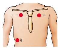
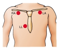
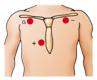
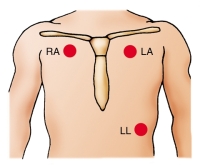
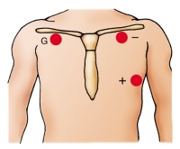
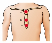
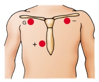
| POSITIONING MONITORING LEADS | ||
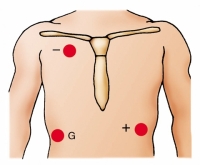
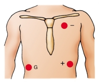
| This chart shows the correct electrode positions for some of the monitoring leads you will use most often. For each lead, you will see electrode placement for a fivelead wire system, a threelead wire system, and a telemetry system. In the two hardwire systems, the electrode positions for one lead may be identical to the electrode positions for another lead. In this case, you simply change the lead selector switch to the setting that corresponds to the lead you want. In some cases, you will need to reposition the electrodes. In the telemetry system, you can create the same lead with two electrodes that you do with three, simply by eliminating the ground electrode. The illustrations below use these abbreviations: RA, right arm; LA, left arm; RL, right leg; LL, left leg; C, chest; G, ground. | ||
| FiveLead Wire System | ThreeLead Wire System | Telemetry System |
Lead I 
|

|
|
Lead II 
|

|
|
Lead III 
|

|
|
Lead MCL 1 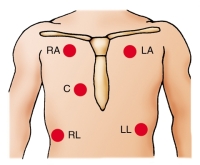
|
|
|
Lead MCL 6 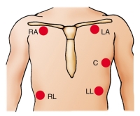
|
|
|
Sternal lead 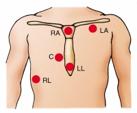
|

|
|
Blake lead 
|

|
|
 TROUBLESHOOTING TROUBLESHOOTINGIDENTIFYING CARDIAC MONITOR PROBLEMS |
||
| Problem | Possible Causes | Solutions |
| False high-rate alarm | Monitor interpreting large T waves as QRS complexes, which doubles the rate | Reposition electrodes to lead where QRS complexes are taller than T waves. Decrease the gain, if necessary. |
| Skeletal muscle activity | Place the electrodes away from major muscle masses. | |
| False low-rate alarm | Shift in electrical axis from client movement, making QRS complexes too small to register | Reapply the electrodes. Set gain so that the height of the complex is greater than 1 millivolt. |
| Low amplitude of QRS | Increase the gain. | |
| Poor contact between electrode and skin | Reapply the electrodes. | |
| Low amplitude | Gain dial set too low | Increase the gain. |
| Poor contact between skin and electrodes; dried gel; broken or loose lead wires; poor connection between client and monitor; malfunctioning monitor; physiologic loss of QRS amplitude | Check the connections on all lead wires and monitoring cable. Replace the electrodes as necessary. | |
| Wandering baseline | Poor position or contact between electrodes and skin | Reposition or replace the electrodes. |
| Thoracic movement with respirations | Reposition the electrodes. | |
| Artifact (waveform interference) | Client having seizures, chills, or anxiety | Notify the physician and treat the client as ordered. Keep the client warm and provide reassurance. |
| Client movement | Help the client to relax. | |
| Electrodes applied improperly | Check the electrodes and reapply them, if necessary. | |
| Static electricity | Make sure that the cables do not have exposed connectors. Change the client's static-causing gown or pajamas. | |
| Electrical short circuit in lead wires or cable | Replace the broken equipment. Use stress loops when applying lead wires. | |
| Interference from decreased room humidity | Regulate the humidity to 40%. | |
| Broken lead wires or cable | Stress loops not used on lead wires | Replace the lead wires and retape them using stress loops. |
| Cables and lead wires cleaned with alcohol or acetone, causing brittleness | Clean the cable and lead wires with soapy water. Do not allow cable ends to become wet. Replace the cable as necessary. | |
| 60-cycle interference (fuzzy baseline) | Electrical interference from other equipment in room | Attach all electrical equipment to a common ground. Check the plugs to make sure the prongs are not loose. |
| Client's bed improperly grounded | Attach the bed ground to the room's common ground. | |
| Skin excoriation under electrode | Client allergic to electrode adhesive | Remove the electrodes and apply nonallergenic electrodes and nonallergenic tape. |
| Electrode on skin too long | Remove the electrode, clean the site, and reapply the electrode at a new site. | |